Corporate ¤ Home ¤ License ¤ Memory ¤ MIPs ¤ Performance ¤ Products ¤ Prices
![]()
Corporate ¤ Home ¤ License ¤ Memory ¤ MIPs ¤ Performance ¤ Products ¤ Prices |
|
Low Rate Data Modem System Description and Specifications
Click on the links below for detailed information, downloads, etc.
AT Commands ¤ Block Diagram ¤ Command Handler ¤ Data Handler ¤ S Registers ¤ Sequencer ¤ User Manual
Overview
The Low Rate Data Modem System implements a complete low rate (14,400 bits/sec. and below) data modem system on a DSP chip. It has been developed as a general purpose DSP replacement for chipset modems that are either inflexible or no longer available. It's a system framework that is designed to let you mix and match Components to tailor a modem system that fits your needs and your budget without having to purchase or store the code for un-needed elements. As an example, you can build a complete 14,400 bits/sec. modem with v.42 error control and fallbacks to 1,200 bits/sec. using the Low Rate Data Modem System software, and the Data Bundle (v.32bis, v.22bis, GenDet) and V.42 Components (see price.htm). Alternatively, if you only needed 2,400 bits/sec. v22bis, then you would only need to buy the Low Rate Data Modem System software and the v.22bis Object Code Component. This system would be small enough to fit entirely on-chip on a Texas Instruments TMS320C5402 or Analog Devices ADSP2185M DSPs with no external RAM. Since the Low Rate Data Modem System software and the modem components are sold separately, you can mix-and-match Object Code, Assembly and/or C Source to balance your cost/code access requirements.
Key features
- Complete software solution - just link in the desired Components, boot the code, and make CALL and ANSWER
mode data connections.
- Complete hardware solution requires only:
DSP chip
1 clock oscillator module for DSP and UART baud
clock
1 quad RS-232 level translator (not needed if
interfacing through host port)
Data Access Arrangement (audio codec + phone line
interface) such as Silicon Labs Si3035 .
Boot PROM (not needed if booting through host
interface port)
- V.24 interchange circuits can be brought out to an external register or flag
pins.
- Synchronous data interface built-in
- V.14 async-to-sync converter built-in
- V.42 error control Component option
- V.32bis, V.22bis, V.21, Bell212a, Bell103, Baudot modem Component options.
- CallerID, DTMF detect Component options.
- software UART up to 115,200 bits/sec. through serial port with CTS/RTS flow
control.
- Run-time "baby AT" command set:
ATA, ATD<dialstring>,
ATE<>, ATH, ATM<>, ATN<rate>, ATO, ATZ, A/,
+++
- Compile-time AT S-register configurations.
- Alternate host port command/data interface option.
- Real-time dual-DAC constellation display support.
- Real-time data logging facility.
- Multi-channel ready - you can fit 24 channels (v22bis @ 2,400 bits/sec) on a
single T.I. DSP!
- Audio codec drivers provided for:
AD1847, AD73311, Crystal CS4216, Silicon Labs Si3035, Si3044,
TLC320C44, TLC320AC01, TLC320AD50
- Entry point provided in scheduler for user function calls with complete
channel memory-access pointer.
The internal connections, buffers, and function blocks are shown in the block diagram below:
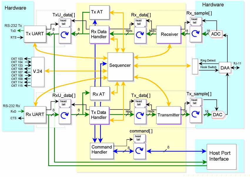
Low Rate Data Modem System Block Diagram
The Low Rate Data Modem System implements a "baby" AT command set that implements several industry standard AT commands. These commands are sent to the system through the software UART from an RS-232 connected terminal device. They allow you to alter the operation of the modem in real-time.
| Command | Response | Function | Default | Parameters/Description |
| A/ | none | Re-execute command | n/a |
Forces the system to re-execute the previous command(s). |
| A<n> | OK | Auto Answer modes | 1 | If the parameter is non-zero, ATA<n> puts the
system in auto-answer mode and answer incoming call after the specified
number of rings are detected. In the special case where "n" is zero
then ATA0 has dual functionality. If auto-answer mode is enabled, then
ATA0 only disables auto-answer mode (analogous to conventional "ATS0=0").
If auto-answer mode is disabled, then ATA0 causes the modem to immediately go
off hook and attempt to connect (analogous to conventional "ATA" command). In this case, the "wait for ringing"
detection is by-passed and the modem immediately starts to generate the
appropriate ANSWER-mode initiation sequence (i.e. it puts out 2100 Hz
ANSWER tone). ATA0 is useful for trunk-based and cellular modes where
there is no audible ring-back associated with call setup. n=0 » disable auto-answer if auto-answer is currently enabled n=0 » go off-hook and connect if auto-answer is currently disabled n=1 » Auto answer after 1 ring |
| B<n> | OK | Select ITU/Bellcore mode | 0 | Selects between ITU V.22 and Bell212a modem
standards for rate=1200 bits/sec., and between ITU V.21 and Bell103 modem
standard for rate=300 bits/sec. n=0 » enable ITU (v.22 and v.21) modem mode n=1 » enable Bellcore (Bell212a and Bell103) modem mode |
| C<n> | OK | Enable digit detection mode | 0 | Enables or disables digit detection (DTMF or
R1) and reporting. If enabled, the system will listen for digits in
parallel with standard modem startup operation. n=0 » disable digit detection (default) n=1 » enable DTMF digit detection mode n=2 » enable MF R1 digit detection mode |
| AT | OK | Command line prefix |
n/a |
Attention Code. Precedes all commands except for the "A/" (repeat command) and "+++" (escape sequence). |
| D<dial string> | OK | DTMF Dial digit string | n/a | DTMF dial command causes the system to go off-hook, check for dial tone, and dial the digits specified in <dial string>. Valid dial string characters are: 0 to 9, A to D, #, *, and "," (comma=2 sec. pause). In 4-wire mode, used for trunk-based and cellular connections, the ATD command can be used with no dial string supplied to force the modem to go immediately to search for ANSWER from the responder. This bypasses the wait for billing delay and dial-tone. |
| DT<dial string> | OK | DTMF Dial digit string | n/a | DTMF dial command causes the system to go off-hook, check for dial tone, and dial the digits specified in <dial string>. Valid dial string characters are: 0 to 9, A to D, #, *, and "," (comma=2 sec. pause). |
| E<n> | OK
|
Terminal Command Echo | n=1 | Terminal Character Echo - enables or disables
echo of characters sent to the modem. n=0 » disable character echo n=1 » enable character echo |
| H | OK
|
Hang Up | n/a | Hang Up command causes the system to terminate a call. In v32bis, a "GSTN cleardown" rate pattern is sent, and the system hangs up within 5 seconds. In v22bis the modem transmits silence and hangs up immediately. |
| M<n> | OK | Data Handler Select | n=0 | Data Handler Select command determines the
type of data processing on the rate data to and from the modem component. n=0 » V.14 sync-to-async converter - start/stop bit framing, no error control n=1 » synchronous mode - no error control n=4 » V.42 error control - LAPM protocol |
| N<rate> | OK
|
Modem Bit Rate | 14,400 | Modem Bit Rate command selects the modem data
signaling rate in bits/sec. V.32bis auto-mode fallback to v22bis is
automatically enabled if v.22bis component is available (i.e. built into
the system). Invalid rates are ignored and the rate is unchanged n=300 » V.21 300 bits/sec. n=1200 » V.22bis 1,200 bits,sec. n=2400 » V.22bis 2,400 bits,sec. n=4800 » V.32bis 4,800 bits,sec. n=7200 » V.32bis 7,200 bits,sec. n=9600 » V.32bis 9,600 bits,sec. n=12000 » V.32bis 12,000 bits,sec. n=14400 » V.32bis 14,400 bits,sec. |
| O | OK | Return to Online | n/a | Online command causes the data handler to switch back to the online state and restores the data link. This command is only effective if the modem is currently connected and is in command mode as thge result of an escape sequence, +++ |
| V<n> | OK | Verbose | n=1 | Verbose command causes results to be
displayed in verbose mode (i.e. OK, CONNECT, etc.). Supports standard
modem init strings, and the parameter is currently ignored n=1 » enable verbose mode |
| Z | none | Software Reset | n/a | Software Reset causes the system to return to a reset state (on-hook and all command parameters at default). This command will not echo since it resets the command handler. |
The AT Command Handler is separated into transmit and receive (Tx and Rx) sections operating independently to process AT commands from the user, and pass command responses and status messages to the user. The Rx-AT Command Handler section physically monitors the data stream going from the UART to the modem's transmit data buffer. When in the off-line state, it constantly checks the data for the presence of the "A" and "T" ascii character sequence, which signifies the "attention" command from the user. Upon receipt of these attention characters, the subsequent characters are evaluated against a list of valid commands and parameters that the Low Rate Data Modem system responds to. Please see AT Commands for a summary table of these commands. If a valid command is detected, the corresponding LRDM command is issued to the Command Handler for system evaluation and execution. The Tx-AT Command Handler monitors the system Command Handler for execution status, and reports "OK" or "ERROR" messages back to the user indicating either successful execution or failure to execute the last command. The Tx-AT Command Handler also echoes all characters back to the user if enabled.
The Command Handler is a top-level process that is invoked by the system framework to interpret system commands and execute them. It includes a function call from the system scheduler to a command processor, and a circular command buffer that contains formatted commands. Commands are written to the command buffer by the AT Command Handler in response to a valid AT command, or directly by the user via the processor's host port interface, or other memory access mechanism. Command codes and the command buffer format are specified in the command.h header file. Some examples of LRDM commands are:
Commands are formatted with a 3 byte header and optional parameter bytes, and includes a channel specifier to allow a single command structure to control multi-channel implementations of the LRDM. In systems where the LRDM is implemented in a DSP attached to a host processor via a "host port interface" (please refer to specific DSP devices for HPI), the host can issue commands to the LRDM via the command buffer, and disable the AT Command Handler and software UART.
The Data Handler is a top-level process that is invoked by the system framework to manage the transmission of actual message data between the line (i.e. the modem connected to the telephone) and the user interface (i.e. the UART or direct command interface). Initially the Data Handler is in an "Idle" state where it simply returns to the caller- no data are passed. Upon connection to the line, the Data Handler is switched into one of several possible processing states, and transfers message data. Possible Data Handler devices include:
The default condition for the Data Handler is to enable the highest level device present in the system. If the Low Rate Data Modem has been built with the v.42 error control component included, then it will be enabled by default and LAPM will be negotiated immediately upon connection with a remote modem. Bytes will only be transferred to/from the UART if they are present and error-free in a data frame. If built with only the v.14 converter present, then only start/stop bit framing will be provided upon connection with a remote modem. Again, asynchronous bytes will only be transferred to/from the UART if start bit has been detected. If the v.24 synchronous interface is included, then the data stream is passed directly to clock and data pins with no framing or data processing. Synchronous data are continuously transferred to/from the user I/O at the channel bit rate regardless of the data contents.
The Sequencer is a top-level process that is invoked by the system framework to implement the call setup, tear-down, and management state machine. It consists of a set of functions executing directly from the system scheduler, that sequence the LRDM through the state processes required to connect to the phone line and establish a data transfer session with a remote terminal. The Sequencer is initialized to an "idle" state upon reset, and always returns to idle upon completion of a call. When the LRDM is commanded to make a connection (i.e. ATA or ATDT commands), then the Command Handler forces the Sequencer to transition from "idle" state to an action state, such as "Seq_wait_for_ring" or "Seq_wait_for_dialtone". The Sequencer then transitions through the prescribed states required to establish the data connection and maintain it. Most Sequencer states also include timeout conditions derived from S-register timeout values that force the command handler to tear down a call and return to "idle". Sequencer states contain the "next-state" transition information internally without access to a soft state table, so users can implement external processing states by a single state function pointer override.
The Low Rate Data Modem System implements several of the industry standard S Register functions in firmware. These registers contain the default characters and values used by the AT command handler, and since they are "firmware", they can be modified at compile/assembly time. The table below summarizes the S Registers available.
| S Register | Function | Default | Description |
| 0 | Rings to answer | 1 | Specifies the number of rings required before the modem will go off-hook after an ATA command has put the system in Auto-Answer mode. |
| 2 | Escape Characters | +++ | Specifies the character used in the escape sequence. |
| 3 | Command Terminate Character | CR | Specifies the character used to terminate a command string. The default is a carriage return, CR. |
| 4 | Line Feed Character | LF | Specifies the character used to force a terminal line-feed. The default is a line feed, LF. |
| 5 | Back Space Character | BS | Specifies the character used to back the curser to it's previous position - one position to the left. The default is a back-space, BS. |
| 6 | Wait Time For dial tone | 2 Sec. | Specifies the timeout for dial tone to be detected after the system has gone off-hook. |
| 7 | Wait Time For Carrier | 30 sec. | Specifies the timeout for the detection of a modem carrier after the system has dialed or answered. |
| 8 | DTMF Pause Duration | 2 sec. | Specifies the duration of silence generation for a dial string pause character, ",". |
| 9 | Carrier Detect Time | 600 msec. | Specifies how long a carrier must be present for the modem to confirm it's detection, in units of 1/10 sec. |
| 10 | Carrier Loss Time | 700 msec. | Specifies how long a carrier must be absent for the modem to initiate termination of a call, in units of 1/10 sec. |
| 11 | DTMF Tone Duration | 63 sec. | Specifies the duration of a DTMF digit tone pair, in units of 1/100 sec |
| 12 | Escape Code Guard Time | 1.0 sec. | Specifies the minimum silence interval preceding and following an escape sequence (+++), and the maximum gap between any two consecutive escape characters. Specified in units of 1/50 sec. |